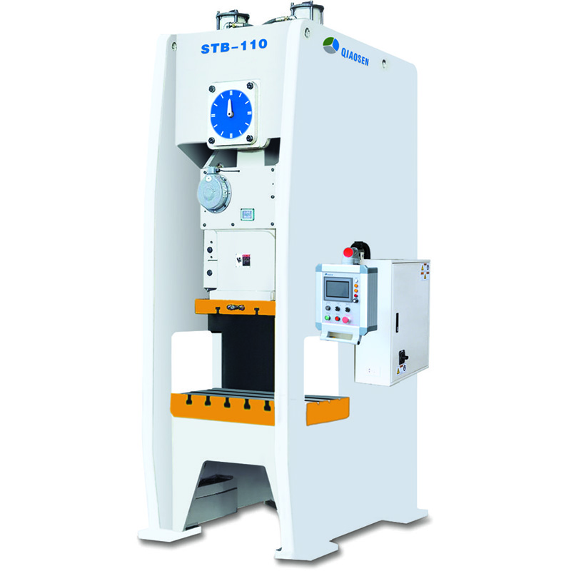
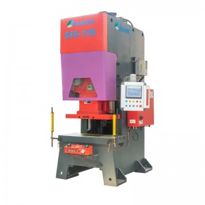
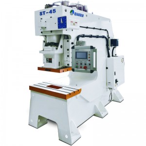
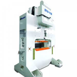
D Frame Single Crank Press Machine(STB-Series)
Main performance characteristics:
1. High strength frame structure, small deformation and high precision.
2. Use OMPI pneumatic dry clutch and brake.
3. The slider adopts two-corner six-sided guide path, and the slider guide adopts "high-frequency hardening" and "rail grinding process": low wear, high precision, long precision retention time, and improved mold life.
4. The crankshaft is made of high-strength alloy material 42CrMo, which is 1.3 times stronger than 45 steel and has a longer service life.
5. The copper sleeve is made of tin-phosphorus bronze ZQSn10-1, whose strength is 1.5 times higher than that of ordinary BC6 brass.
6. The use of highly sensitive hydraulic overload protection device can effectively protect the service life of the punch and die.
7. Optional mold cushion (air cushion).
Standard configuration
|
1 |
Hydraulic overload protection device |
12 |
Second falling protection device |
|
2 |
Manual slider adjustment device (below ST60) |
13 |
Air blowing device |
|
3 |
Electric slider adjusting device (above ST80) |
14 |
Mechanical shockproof feet |
|
4 |
Variable frequency variable speed motor (adjustable speed) |
15 |
Reserved interface for wrong delivery detection device |
|
5 |
Mechanical mold height indicator (below ST60) |
16 |
Maintenance tools and toolbox |
|
6 |
Digital mold height indicator (above ST80) |
17 |
Main motor reversing device |
|
7 |
Slider and mold balance device |
18 |
Photoelectric safety protection device |
|
8 |
Rotating cam controller |
19 |
Power outlet |
|
9 |
Crankshaft angle indicator |
20 |
Electric grease lubrication device |
|
10 |
Electromagnetic counter |
21 |
Touch screen (pre-break, pre-load) |
|
11 |
Air source connector |
22 |
Wet clutch |
Optional Configuration
|
1 |
Pneumatic mold pad device |
7 |
Leveling machine |
|
2 |
Die height electric adjusting device |
8 |
Manipulator |
|
3 |
Quick die change device (Die lifter, die clamper or die mover) |
9 |
Rack |
|
4 |
Mobile two handed console |
10 |
Thin oil lubrication device |
|
5 |
Upper part hit material device of slider |
11 |
Foot switch |
|
6 |
Feeder (air, mechanical and NC) |
12 |
Dry clutch |
Technical parameter
| Name | Unit | STB-80 | STB-110 | STB-160 | STB-200 | STB-260 | STB-315 | ||||||
| Mode | V-type | H-type | V-type | H-type | V-type | H-type | V-type | H-type | V-type | H-type | V-type | H-type | |
| Press capacity | Ton | 80 | 110 | 160 | 200 | 260 | 315 | ||||||
| Impact force location | mm | 4 | 2 | 6 | 3 | 6 | 3 | 6 | 3 | 7 | 3.5 | 7 | 3.5 |
| Slider strokes per minute | S.P.M | 35~80 | 80~120 | 30~60 | 60~90 | 20~50 | 40~70 | 20~50 | 50~70 | 20~40 | 40~50 | 20~40 | 40~50 |
| Slider stroke length | mm | 150 | 70 | 180 | 80 | 200 | 90 | 200 | 100 | 250 | 150 | 280 | 170 |
| Max mold height | mm | 340 | 380 | 360 | 410 | 460 | 510 | 460 | 510 | 500 | 550 | 520 | 600 |
| Slider adjustment amount | mm | 80 | 80 | 100 | 110 | 120 | 120 | ||||||
| Up platform size | mm | 560*420*70 | 650*470*80 | 700*550*90 | 850*630*90 | 950*700*100 | 1000*750*100 | ||||||
| Down platform size | mm | 760*550*90 | 900*600*110 | 980*880*140 | 1140*820*160 | 1500*840*180 | 1600*840*180 | ||||||
| Slider center to machine distance | mm | 280 | 305 | 405 | 415 | 430 | 430 | ||||||
| Platform to floor distance | mm | 830 | 830 | 900 | 995 | 1030 | 1030 | ||||||
| Shank hole | mm | Φ50 | Φ50 | Φ65 | Φ65 | Φ65 | Φ65 | ||||||
| Main motor power | KW*P | 7.5*4 | 11*4 | 15*4 | 18.5*4 | 22*4 | 30*4 | ||||||
| Slider adjust device | / | Electric | |||||||||||
| Air pressure | kg*cm² | 6 | 6 | 6 | 6 | 6 | 6 | ||||||
| Press accuracy grade | Grade | JIS 1 | JIS 1 | JIS 1 | JIS 1 | JIS 1 | JIS 1 | ||||||
| Press dimension(L*W*H) | mm | 1300*1890*3000 | 1420*1985*3200 | 1600*2200*3500 | 1750*2500*3900 | 2080*2895*4470 | 2100*2925*4550 | ||||||
| Press weight | Tons | 7.8 | 10.5 | 17.8 | 25.3 | 37 | 42 | ||||||
| Die cushion capacity | Ton | 3.6 | 6.3 | 10 | 14 | 14 | 14 | ||||||
| Die cushion Stroke | mm | 70 | 80 | 80 | 100 | 100 | 100 | ||||||
| Die cushion active area | mm² | 450*310 | 500*350 | 650*420 | 710*480 | 810*480 | 810*480 | ||||||


